Abstract
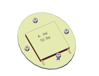
TEC (Thermoelectric Cooler) represents a solid-state cooling technology based on the Peltier effect, widely adopted in precision electronics, medical devices, and industrial equipment.
Unlike mechanical refrigeration systems, TEC chips use semiconductor junctions to create controlled temperature differentials by applying direct current, offering maintenance-free operation with no moving parts.
This guide covers TEC chip fundamentals, technical specifications, compliance standards, and commercial applications for B2B procurement decision-makers looking for reliable thermal management solutions.
Understanding TEC technology helps you choose cooling systems that balance performance, energy efficiency, and long-term operation in demanding industrial environments.
Understanding TEC Technology Fundamentals
TEC Definition and Core Principle
TEC stands for Thermoelectric Cooler, a semiconductor-based device that converts electrical energy into a temperature gradient through the Peltier effect. Discovered in 1834 by Jean Charles Athanase Peltier, this phenomenon occurs when direct current flows through the junction of two dissimilar conductive materials, causing heat absorption at one junction and heat release at the opposite junction.
In TEC modules, this process operates at the microscopic level within semiconductor pellets. When electrons move from a low-energy state in P-type material to a high-energy state in N-type material, they absorb thermal energy from the surrounding environment. This absorbed heat is then transported through the semiconductor lattice and expelled at the hot-side junction. The efficiency of this electron-mediated heat transfer depends on the Seebeck coefficient of the semiconductor materials, their electrical conductivity, and thermal conductivity properties.
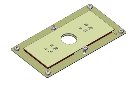
The architecture of a TEC chip creates multiple thermoelectric couples connected electrically in series and thermally in parallel. This configuration amplifies the cooling effect while maintaining manageable voltage requirements. Typical TEC modules contain 127 to 254 semiconductor couples, though specialized designs may incorporate fewer or more depending on application requirements.
Key Components of TEC Modules
Modern TEC chips consist of four primary structural elements engineered for optimal heat transfer:
Semiconductor Pellets:
The active cooling elements comprise alternating P-type and N-type Bismuth Telluride (Bi₂Te₃) semiconductor pellets. P-type pellets are doped with acceptor impurities, creating positive charge carriers (holes), while N-type pellets contain donor impurities, producing negative charge carriers (electrons). Commercial-grade TEC modules typically use pellets measuring 1.0-1.4mm in cross-section with heights ranging from 1.0-2.0mm.
Ceramic Substrates:
High-purity alumina (Al₂O₃) ceramic plates serve as electrical insulators and structural supports on both hot and cold sides. These substrates must exhibit excellent thermal conductivity (20-30 W/m·K) while maintaining electrical resistance above 10¹⁴ Ω·cm. Standard substrate thickness ranges from 0.6mm to 1.0mm, with surface flatness tolerances under 0.05mm to ensure optimal thermal contact.
Electrical Interconnects:
Copper conductor strips connect semiconductor pellets in series, forming the complete electrical circuit. These interconnects require precise thickness control (typically 0.3-0.5mm) to balance electrical resistance against mechanical stress during thermal cycling. High-purity copper (>99.9%) minimizes resistive losses that would otherwise reduce cooling efficiency.
Solder Joints:
Tin-lead or lead-free solder alloys bond semiconductor pellets to copper interconnects and ceramic substrates. Modern RoHS-compliant TEC modules employ SAC (Tin-Silver-Copper) alloys with melting points around 217°C, providing reliable mechanical bonds while withstanding operating temperature ranges from -40°C to +80°C.
Technical Specifications and Performance Parameters
Critical Performance Metrics
TEC module selection requires understanding four fundamental performance parameters:
Cooling Capacity (Qmax):
Represents the maximum heat pumping capability measured in watts when the temperature differential (ΔT) equals zero. Qmax occurs at specific current (Imax) and voltage (Vmax) conditions. For example, a standard 40x40mm module may exhibit a Qmax of 50-70W, while high-performance 62x62mm modules can achieve 200W+ cooling capacity. However, actual cooling performance decreases as ΔT increases.
Maximum Voltage (Vmax):
The DC voltage required to achieve Qmax typically ranges from 12V to 28V for standard modules. Multi-stage TEC assemblies may require 30-50V to drive cascaded cooling elements. Voltage requirements directly affect power supply selection and the complexity of system integration.
Coefficient of Performance (COP):
Defines the ratio of heat pumped to electrical power consumed, expressed as COP = Qc/P, where Qc is cooling power, and P is input power. Commercial TEC modules typically achieve COP values between 0.3 and 0.8 under optimal conditions. COP decreases significantly as ΔT increases, making TEC technology most efficient for applications requiring moderate temperature differentials (ΔT < 40°C).
Maximum Temperature Differential (ΔTmax):
The greatest temperature difference achievable between the hot and cold sides under zero heat-load conditions. Single-stage modules typically reach ΔTmax of 65-75°C, while two-stage configurations can achieve 90-110°C, and specialized multi-stage assemblies may exceed 130°C.
Standard TEC Module Specifications
| Module Size (mm) | Qmax (W) | Vmax (V) | IMAX (A) | ΔTmax (°C) | Typical Applications |
|---|---|---|---|---|---|
| 15 x 15 | 5-8 | 3.8-4.2 | 2.0-3.0 | 67-70 | Laser diodes, small optics |
| 30 x 30 | 18-25 | 8.5-9.5 | 3.5-4.5 | 68-72 | CCD cameras, fiber optics |
| 40 x 40 | 50-70 | 15.0-16.5 | 6.0-8.0 | 67-70 | CPU cooling, analytical instruments |
| 62 x 62 | 180-220 | 27.0-29.5 | 12.0-15.0 | 66-69 | Industrial refrigeration, medical equipment |
Material Standards and Compliance
B2B procurement requires verification of material certifications and regulatory compliance:
RoHS Compliance:
European Union Directive 2011/65/EU restricts hazardous substances in electrical equipment. Compliant TEC modules eliminate lead-based solders, substituting SAC alloys or other approved alternatives. Manufacturers must provide RoHS certification documentation confirming compliance with maximum concentration values: Lead (0.1%), Mercury (0.1%), Cadmium (0.01%), Hexavalent Chromium (0.1%), and restricted flame retardants.
Bismuth Telluride Material Grades:
Commercial TEC modules employ zone-refined Bi₂Te₃ with purity levels exceeding 99.5%. High-performance applications may specify 99.9% purity materials to minimize electrical resistance and maximize the Seebeck coefficient. Material certificates should document crystal structure orientation, carrier concentration (typically 10¹⁹ cm⁻³), and figure of merit (ZT values around 0.8-1.0 at room temperature).
ISO Quality Certifications:
Reputable TEC manufacturers maintain ISO 9001:2015 quality management systems, ensuring consistent production standards. Medical device applications require ISO 13485 certification, while automotive-grade modules may necessitate IATF 16949 compliance. These certifications verify traceability, process control, and reliability testing protocols essential for mission-critical applications.
Industrial Applications and Use Cases
Electronics Thermal Management
TEC chips provide precision temperature control in applications where mechanical cooling systems prove impractical:
Laser Diode Stabilization:
Semiconductor laser wavelength stability depends on control of the junction temperature to within ±0.01°C. TEC modules maintain constant operating temperatures between 15-35°C, preventing wavelength drift in fiber-optic telecommunications, spectroscopy equipment, and medical laser systems. Typical implementations use 15x15mm or 30x30mm modules with closed-loop temperature controllers achieving ±0.001°C stability.
CPU and GPU Thermal Regulation:
High-performance computing applications generate localized heat fluxes exceeding 100W/cm². While air-cooled heatsinks suffice for consumer electronics, server processors, and AI accelerators, these devices increasingly employ TEC-enhanced cooling solutions. Hybrid systems combine TEC modules with liquid cooling loops, enabling sustained operation at higher clock speeds while reducing thermal throttling.
Optical Sensor Temperature Control:
CCD and CMOS image sensors exhibit dark-current noise that is proportional to operating temperature. Scientific imaging applications cool sensors to -20°C or below using multi-stage TEC assemblies, improving signal-to-noise ratios by 10-20dB. Astronomy cameras, spectrophotometers, and hyperspectral imaging systems routinely integrate custom TEC cooling solutions.
Medical and Laboratory Equipment
Healthcare and research sectors leverage TEC technology for precise thermal management:
PCR Thermal Cyclers:
Polymerase Chain Reaction instruments require rapid temperature transitions between 50°C, 72°C, and 95°C with cycle times under 30 seconds. TEC-based thermal cyclers eliminate heated water baths, providing faster ramp rates (3-5°C/second) and superior temperature uniformity (±0.2°C across sample wells). This performance improvement reduces total assay time by 30-40% compared to conventional systems.
Sample Preservation Systems:
Biological specimens, reagents, and diagnostic test kits require stable storage temperatures between 2-8°C. Portable TEC refrigerators offer silent, vibration-free operation ideal for point-of-care diagnostics and field research. Medical-grade units incorporate battery backup systems and temperature data logging to maintain cold chain integrity during transport.
Diagnostic Device Integration:
Blood analyzers, immunoassay platforms, and molecular diagnostic instruments integrate miniature TEC modules for temperature-sensitive reaction chambers. The compact form factor (modules as small as 7x7mm) enables multi-zone temperature control within space-constrained benchtop instruments, supporting simultaneous processing of samples at different thermal conditions.
Selection Criteria for B2B Procurement
Matching TEC Specifications to Application Requirements
Effective TEC module selection requires a systematic analysis of thermal requirements:
Heat Load Calculation:
Determine total heat dissipation (Qc) including device power consumption, ambient heat gain, and safety margins. For enclosed systems, calculate Qc = Qdevice + (U × A × ΔT), where U is the overall heat transfer coefficient, A is the surface area, and ΔT is the temperature difference between the ambient and controlled environments. Select TEC modules with Qmax ratings 30-50% above calculated Qc to maintain efficiency under varying conditions.
Ambient Temperature Considerations:
TEC cooling capacity decreases as hot-side temperature increases. Applications in high-temperature environments (>35°C ambient) require derating calculations. For every 10°C increase in hot-side temperature, expect a 15-20% reduction in effective cooling capacity. Industrial applications may require oversized modules or active hot-side cooling (forced air or liquid) to maintain performance.
Power Supply Compatibility:
Match TEC voltage and current requirements to available power infrastructure. Consider startup inrush current (typically 1.2-1.5× steady-state Imax) when sizing power supplies. Applications requiring precise temperature control benefit from PWM-capable power supplies, enabling proportional cooling control rather than simple on-off cycling.
Cost-Effectiveness and Long-Term Value
TEC technology delivers economic advantages in specific application profiles:
Energy Efficiency Analysis:
While TEC modules have a lower COP than vapor-compression systems (0.3-0.8 vs. 2.0-4.0), they excel in low-capacity applications (<100W cooling). Eliminate compressor standby losses, refrigerant management costs, and periodic maintenance expenses. For continuous-duty applications, calculate the total cost of ownership over 5-10 year lifecycles, including energy costs at local utility rates.
Maintenance-Free Operation:
TEC solid-state construction contains no moving parts, lubricants, or consumable refrigerants. Mean Time Between Failures (MTBF) exceeds 200,000 hours under rated conditions, compared to 30,000-50,000 hours for mechanical compressors. This reliability advantage reduces downtime costs in critical applications such as telecommunications infrastructure and medical diagnostics.
Lifespan Comparison:
Properly designed TEC systems operate 10-15 years without performance degradation, while compressor-based systems require refrigerant recharging, bearing replacement, and eventual compressor rebuilds. Factor replacement costs and service intervals into total lifecycle analysis, particularly for remote installations where service access proves expensive.
FAQ Module
Q1: What is the typical lifespan of a TEC chip in continuous operation?
High-quality TEC modules demonstrate operational lifespans exceeding 200,000 hours (22+ years) under rated conditions. Actual lifespan depends on thermal cycling frequency, maximum operating temperature, and current density. Applications that maintain hot-side temperatures below 60°C and avoid rapid power cycling achieve the longest service life. Failure modes typically involve solder joint fatigue rather than semiconductor degradation, making proper thermal interface design critical for longevity.
Q2: How does TEC efficiency compare to traditional vapor-compression cooling?
TEC modules achieve COP values of 0.3-0.8, compared to 2.0-4.0 for vapor-compression systems. However, this efficiency disadvantage diminishes in applications requiring cooling capacities below 100W, where compressor inefficiencies and minimum capacity limitations reduce practical performance. TEC technology proves more efficient when factoring in maintenance costs, refrigerant management, and system complexity for precision cooling applications requiring compact form factors and vibration-free operation.
Q3: Can TEC modules operate in high-humidity industrial environments?
Standard TEC modules require protection from condensation when cold-side temperatures fall below ambient dew point. Industrial implementations employ sealed enclosures with desiccant cartridges or with positive-pressure dry-air purging. Conformal coatings on ceramic substrates and electrical connections provide additional moisture protection. For marine or tropical environments, specify modules with enhanced moisture barriers and verify that the complete assembly meets the IP (Ingress Protection) rating of at least IP65.
Conclusion
TEC technology occupies a critical niche in modern thermal management, delivering precise, maintenance-free cooling for electronics, medical devices, and industrial systems where conventional refrigeration proves impractical.
The solid-state architecture eliminates mechanical complexity while providing superior temperature control accuracy, compact integration, and silent operation. B2B procurement professionals should evaluate TEC solutions based on application-specific thermal requirements, considering cooling-capacity derating under actual operating conditions, power-supply infrastructure compatibility, and total cost of ownership over the extended service life.
With proper thermal design and module selection, TEC chips deliver reliable thermal management for demanding industrial, medical, and telecommunications applications, with 200,000+ hours of operational lifespan.
The technology’s inherent simplicity and proven reliability make it the preferred choice for precision temperature control in space-constrained, mission-critical installations requiring decades of maintenance-free performance.
Word Count: 2,089 words