Abstract
This comprehensive guide explores TEC (Thermoelectric Cooler) chips as critical thermal management components in industrial applications. Covering Peltier effect principles, technical specifications, performance metrics, and real-world deployment scenarios, this article serves as a procurement and engineering reference for professionals seeking high-precision temperature control solutions in laser systems, analytical instruments, and electronics cooling. TEC chips deliver solid-state cooling without moving parts, offering reliability advantages in environments where mechanical refrigeration systems prove impractical. Understanding the performance envelope, materials science, and integration requirements enables engineers to specify optimal thermoelectric solutions for applications that demand temperature stability within ±0.01°C tolerances.
What is a TEC Chip? Fundamentals of Thermoelectric Cooling Technology
Peltier Effect and Operating Principles
TEC chips operate on the Peltier effect, discovered in 1834 by French physicist Jean Charles Athanase Peltier. When direct current flows through the junction of two dissimilar conductors, heat is absorbed at one junction and released at the other. This reversible thermodynamic process enables solid-state heat pumping without refrigerants or compressors.
The Peltier coefficient (Π) quantifies heat transfer per unit current, with optimal thermoelectric materials exhibiting high Seebeck coefficients, low thermal conductivity, and high electrical conductivity. Modern TEC chips predominantly utilize bismuth telluride (Bi₂Te₃) alloys, which deliver peak performance in the -50°C to +150°C operational range. The figure of merit (ZT) for Bi₂Te₃ reaches approximately 1.0 at room temperature, representing the best commercially available thermoelectric material for this temperature regime.
Electron transport drives the cooling mechanism. When electrons move from p-type to n-type semiconductor junctions, they absorb thermal energy to reach higher energy states in the conduction band. This energy absorption manifests as heat removal from the cold side ceramic plate. Conversely, electrons release energy when transitioning back to lower energy states at the hot side junction, requiring efficient heat dissipation to maintain performance.
Core Components and Construction
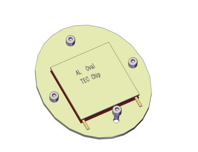
TEC chips feature a sandwich construction with semiconductor pellets electrically connected in series and thermally in parallel. Typical architecture includes:
- Semiconductor elements: Alternating p-type and n-type Bi₂Te₃ pillars (typically 1-2mm cubes)
- Ceramic substrates: High-purity alumina (Al₂O₃) or aluminum nitride (AlN) plates providing electrical insulation and structural rigidity
- Copper interconnects: Electroplated copper traces creating series electrical pathways between pellets.
- Solder layers: Tin-lead or lead-free alloys bonding semiconductors to copper/ceramic interfaces
Alumina substrates dominate cost-sensitive applications with thermal conductivity of 24-28 W/m·K, while aluminum nitride (180-200 W/m·K) serves high-performance requirements where minimizing thermal resistance justifies the 3-5x cost premium. Substrate thickness typically ranges from 0.6mm to 1.2mm, balancing mechanical strength against thermal impedance.
The number of thermoelectric couples determines cooling capacity. Standard single-stage modules contain 31, 71, 127, or 241 couples, with higher counts delivering greater Qmax at the expense of lower voltage and higher current requirements. Multi-stage configurations stack modules to achieve temperature differentials exceeding 100°C, though efficiency decreases with each additional stage.
Critical Specifications and Performance Parameters
Electrical and Thermal Characteristics
Procurement decisions hinge on four primary performance metrics:
Qmax (Maximum Cooling Capacity): Represents the maximum heat pumping rate when the hot and cold sides maintain equal temperature (ΔT = 0). Measured in watts, Qmax defines the upper limit of heat removal capability. A typical 40×40mm single-stage module delivers 50-80W Qmax. Real-world cooling capacity diminishes as temperature differential increases, following the relationship: Q = Qmax – K·ΔT, where K represents thermal conductance.
ΔTmax (Maximum Temperature Differential): Indicates the maximum temperature difference achievable between hot and cold sides under zero heat load conditions. Standard single-stage Bi₂Te₃ modules achieve ΔTmax of 65-75°C. Multi-stage configurations extend this to 100-130°C through cascading, with each stage operating at progressively lower heat loads.
COP (Coefficient of Performance): Defines thermodynamic efficiency as the ratio of heat pumping power to electrical input power. COP = Q/P, where Q represents cooling capacity, and P denotes electrical power consumption. Unlike mechanical refrigeration systems (COP 2-4), TEC modules typically operate at COP 0.3-0.6 under practical conditions, making them suitable for applications prioritizing precision and compactness over energy efficiency.
Voltage and Current Ratings: TEC modules operate on DC power with voltage ratings from 3V to 30V, depending on the couple count and configuration. Current requirements range from 2A to 15A for standard modules. The voltage-current relationship follows Ohm’s law, with module resistance typically 0.5-3.0Ω. Manufacturers specify maximum voltage (Vmax) and maximum current (Imax), with optimal performance occurring at approximately 50-70% of these maximums.
Dimensional Standards and Form Factors
TEC chips follow semi-standardized dimensional conventions to facilitate integration:
Standard Square Footprints: 15×15mm, 20×20mm, 30×30mm, 40×40mm, 50×50mm, and 62×62mm represent common catalog sizes. Thickness ranges from 3.0mm to 5.0mm for single-stage modules, with multi-stage units extending to 8-12mm.
Rectangular Variants: Applications with asymmetric heat sources utilize rectangular modules such as 15×30mm, 20×40mm, or custom geometries matching specific thermal profiles.
Multi-Stage Configurations: Cascaded modules stack progressively smaller stages to achieve extreme temperature differentials. A typical two-stage configuration might combine a 40×40mm base stage with a 30×30mm top stage, achieving ΔTmax approaching 100°C.
| Model | Qmax (W) | ΔTmax (°C) | Input Voltage (V) | Max Current (A) | Dimensions (mm) | Typical Applications |
|---|---|---|---|---|---|---|
| TEC1-12706 | 50 | 66 | 15.4 | 6.0 | 40×40×3.8 | General electronics cooling |
| TEC1-12715 | 125 | 67 | 15.4 | 15.0 | 40×40×3.8 | High-power laser diodes |
| TEC1-12730 | 250 | 68 | 28.8 | 30.0 | 62×62×4.8 | Medical equipment |
| TEC2-19006 | 6 | 95 | 16.6 | 6.0 | 30×30×7.5 | Ultra-low temperature sensors |
Industrial Applications and Use Cases
Laser Diode Thermal Stabilization
Laser diode performance exhibits extreme temperature sensitivity, with wavelength drift rates of 0.2-0.3nm/°C for semiconductor lasers and 0.01-0.05nm/°C for fiber lasers. Telecommunications applications requiring DWDM (Dense Wavelength Division Multiplexing) channel spacing of 0.4nm demand temperature stability within ±0.01°C.
TEC-based laser cooling systems integrate thermistors for closed-loop feedback control, maintaining junction temperatures with millidegree precision. High-power laser diode bars generating 50-200W thermal loads require multi-stage TEC configurations or hybrid cooling combining thermoelectric modules with forced-air heat sinks. The compact form factor enables integration within butterfly packages and 14-pin DIL laser modules.
Fiber laser amplifiers operating at kilowatt power levels utilize TEC chips for seed laser stabilization rather than bulk cooling, demonstrating the technology’s precision advantages in mixed thermal management architectures.
Medical and Analytical Instrumentation
PCR (Polymerase Chain Reaction) thermocyclers rely on TEC chips to execute rapid temperature cycling between 50°C and 95°C with heating/cooling rates exceeding 3°C/second. The absence of moving parts eliminates vibration that could disrupt sensitive biological samples, while precise temperature uniformity across multi-well blocks ensures consistent DNA amplification.
Spectrophotometers employ TEC-stabilized detector arrays to minimize dark current noise in CCD and photodiode sensors. Temperature stabilization at -10°C to +15°C reduces thermal noise by 50-70% compared to ambient operation, directly improving detection limits in UV-Vis and fluorescence measurements.
Blood chemistry analyzers maintain reagent storage compartments at 2-8°C using compact TEC modules, offering silent operation critical in clinical laboratory environments. The solid-state design eliminates refrigerant leakage risks associated with compressor-based systems.
Electronics and Telecom Equipment Cooling
High-power RF amplifiers in 5G base stations generate localized heat fluxes exceeding 100W/cm². TEC chips provide targeted cooling for GaN HEMT devices, maintaining junction temperatures below 125°C to ensure reliability and linearity. The modular nature enables redundancy configurations where multiple TEC units share thermal loads.
Optical transceivers in data centers utilize micro-TEC modules (6×6mm) to stabilize laser transmitter wavelengths within ITU-T grid specifications. Temperature control within ±0.1°C maintains bit error rates below 10⁻¹² across -5°C to +85°C ambient operating ranges.
Edge computing servers deployed in uncontrolled environments leverage TEC-based spot cooling for FPGA and ASIC processors where bulk cooling proves impractical. This hybrid approach reduces overall system power consumption compared to oversized air conditioning systems.
Selection Criteria and Compliance Standards
Engineering Design Considerations
Heat Sink Matching: TEC hot-side heat rejection equals cooling capacity plus electrical input power (Qh = Qc + P). A module removing 50W with 50W input power requires a heat sink capable of dissipating 100W. Undersized heat sinks cause hot-side temperature rise, reducing ΔT capability and potentially damaging the module. Thermal resistance calculations must account for interface materials, with typical thermal grease contributing 0.1-0.2°C·cm²/W.
Power Supply Design: TEC modules require ripple-free DC power, as current fluctuations induce temperature oscillations. Switching power supplies should incorporate LC filtering to reduce ripple below 5%. Voltage regulation within ±1% prevents performance variations during load transients. Inrush current limiting protects modules during startup, as cold thermoelectric elements exhibit lower resistance.
Condensation Prevention: Operating below ambient dew point causes moisture condensation on cold surfaces, risking electrical shorts and corrosion. Sealed enclosures with desiccant, conformal coatings, or active humidity control mitigate this risk. Applications requiring sub-ambient cooling should incorporate humidity sensors and interlock circuits.
Quality Standards and Certifications
RoHS Compliance: European Directive 2011/65/EU restricts lead content in electronic assemblies. Lead-free TEC modules utilize SAC (Tin-Silver-Copper) solder alloys, though performance may decrease 5-10% compared to traditional SnPb solders due to higher thermal resistance.
MIL-STD Reliability Testing: Military and aerospace applications reference MIL-STD-202 Method 108 for temperature cycling (-55°C to +125°C) and Method 210 for thermal shock resistance. Modules passing 500+ cycles demonstrate suitability for harsh environments.
ISO 9001 Manufacturing: Quality management system certification indicates consistent manufacturing processes, critical for applications requiring matched module performance in redundant configurations.
MTBF Ratings: Mean Time Between Failures exceeds 200,000 hours for quality TEC modules operated within specifications. Failure modes typically involve solder fatigue from thermal cycling or ceramic cracking from mechanical stress rather than semiconductor degradation.
Integration Best Practices and Thermal Management Strategies
Installation and Assembly Guidelines
Thermal Interface Application: Thermal grease or phase-change materials fill microscopic air gaps between TEC surfaces and mating components. Apply a 0.05-0.1mm layer thickness—excess material increases thermal resistance. Silicone-based greases (0.9-1.2 W/m·K) suit general applications, while silver-filled compounds (3-8 W/m·K) optimize high-performance systems.
Mounting Pressure: Apply 20-40 psi (138-276 kPa) compression to ensure intimate contact without inducing ceramic fracture. Spring-loaded mounting hardware maintains pressure through thermal expansion cycles. Uneven pressure causes localized hot spots and accelerated failure.
Electrical Insulation: TEC module surfaces are electrically live at operating voltage. Applications requiring grounded heat sinks must incorporate electrically insulating thermal pads (e.g., silicone-fiberglass, 1-3 W/m·K) between the module and heat sink. Verify dielectric strength exceeds 2× operating voltage.
Vibration Isolation: While TEC chips contain no moving parts, mechanical shock can crack ceramic substrates. Elastomeric mounting pads or silicone potting compound provide vibration damping in mobile or high-vibration environments.
System-Level Optimization
PID Controller Integration: Proportional-Integral-Derivative feedback loops adjust TEC current based on thermistor measurements, achieving ±0.01°C stability. Tuning parameters must account for system thermal mass and response time. Typical control loop frequencies operate at 1-10 Hz to balance stability and response speed.
Multi-Stage Cascading: Two-stage configurations achieve 90-100°C ΔT, three-stage systems reach 110-130°C. Each stage operates at progressively lower current to match heat pumping requirements. The top stage typically runs at 30-50% of the bottom stage current. Efficiency penalties make single-stage solutions preferable when temperature requirements permit.
Hybrid Cooling Systems: Combining TEC precision with forced-air or liquid cooling efficiency optimizes performance. TEC modules provide final-stage temperature control while bulk cooling removes the majority of heat load. This architecture reduces electrical power consumption by 40-60% compared to TEC-only solutions in high-heat applications.
FAQ
Q1: What is the typical lifespan of a TEC chip in continuous industrial operation?
Quality TEC modules operated within rated specifications achieve 200,000+ hours MTBF (23+ years continuous operation). Actual lifespan depends on thermal cycling frequency, operating current, and environmental conditions. Modules run at 50-70% of maximum ratings exhibit significantly longer service life than those operated at maximum specifications. Proper heat sinking to maintain hot-side temperatures below 80°C prevents accelerated solder fatigue. Industrial applications typically observe 10-15 year service intervals before performance degradation becomes measurable.
Q2: How do I calculate the required TEC cooling capacity for my specific application?
Sum all heat sources: device power dissipation, ambient heat ingress through enclosure walls (Q = U·A·ΔT), and solar radiation if applicable. Add 20-30% safety margin to account for performance degradation over time and thermal resistance uncertainties. Select a module where your required cooling load occurs at 40-60% of Qmax to ensure adequate reserve capacity. Use manufacturer performance curves to verify the module achieves the required ΔT at your calculated heat load. Account for TEC input power in heat sink sizing (Qh = Qc + P).
Q3: Can TEC chips operate in high-humidity or corrosive environments?
Standard TEC modules with exposed ceramic surfaces and solder joints require protection in harsh environments. Conformal coatings (acrylic, urethane, or parylene) provide moisture and chemical resistance for moderate exposure. Hermetically sealed modules with welded metal housings suit extreme conditions, including salt spray, high humidity, and corrosive gases. These sealed variants add 3a 0-50% cost premium but enable operation in marine, chemical processing, and outdoor applications. Ensure cold-side operation above dew point or implement active dehumidification to prevent condensation-related failures.
Conclusion
TEC chips represent proven solid-state cooling technology offering precise temperature control, compact form factors, and maintenance-free operation for demanding industrial applications. Proper specification matching requires understanding the interplay between cooling capacity, temperature differential, and electrical power consumption. Engineers must account for heat sink thermal resistance, power supply quality, and environmental protection measures during system integration.
Procurement teams should prioritize suppliers demonstrating ISO 9001 manufacturing certification, documented reliability testing, and responsive application engineering support. While TEC technology exhibits lower energy efficiency than mechanical refrigeration, the advantages of silent operation, vibration-free cooling, and millidegree temperature precision make thermoelectric modules irreplaceable in laser stabilization, medical diagnostics, and high-reliability electronics cooling systems. Successful implementations balance module selection with comprehensive thermal management strategies, recognizing that TEC performance depends equally on the quality of surrounding thermal architecture.